Auri System Manual

Introduction
Auri™ powered by Ampetronic and Listen Technologies, is the first Auracast™ broadcast audio-based solution for assistive listening. We have developed Auri to let venues and end users adopt Auracast™ broadcast audio technology now with both dedicated receivers and direct compatibility with newly emerging devices such as hearing aids, earbuds, headphones and mobile phones.
Auri is a comprehensive Assistive Listening System (ALS) that sends high quality, low-latency, multi-channel broadcast audio to an unlimited number of Auracast compatible Receivers and devices.
The system includes Transmitters designed for professional installation, with balanced mic/line inputs and optional integrated Dante. Transmitters broadcast audio to a large area, from two radios with flexible routing options that cover a wide range of project needs. Multiple Transmitters can be used to increase coverage or channel count.
Receivers and Docking Stations meet accessibility needs for all users and allow implementation now while end user devices adopt the latest Bluetooth standards.
The Auri Manager software application provides a user-friendly interface for discovery, management and configuration of all devices over the network.
Auri System Components
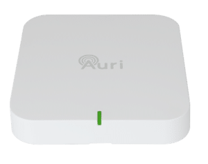
Auri TX2N / Auri TX2N-D Transmitter
The Auri TX2N Auracast Transmitter is the heart of an Auri system, providing long range, low latency Auracast broadcast audio.
A factory option for integrated Dante input is available.
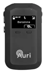
Auri RX1 Receiver
The Auri Audio Receiver is a state-of-the-art assistive listening Receiver, allowing venues to provide hearing assistance to guests while meeting compliance with disability and accessibility requirements.
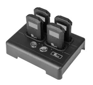
Auri-D4 / Auri-D16 Docking Station
The Docking Stations allow for easy charging and management of Auri Receivers and are available in 4 or 16 unit options, with accessories such as the Docking Station case and intelligent cable management unit for the AURI-D16.
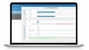
Auri Manager Software Application
The Auri Manager software for Windows® makes setting up the Auri system simple. Easily configure a single device or manage a large system deployed across multiple locations. Auri™ Manager supports automatic discovery, full control and software updates for network-attached Transmitters, charging docks and docked Receivers.
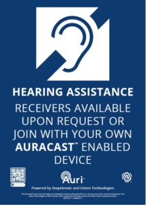
Accessories
A range of compatible accessories are available, including ear speakers and headphones, neck loops and signage.
Safety Instructions
Important Information and Intended Use
Read the following information before you use your Auri System.
This system is a Bluetooth Low Energy Audio Broadcast system operating in the 2.4 GHz frequency band from 2.402 GHz to 2.480 GHz.
The system is designed for use in applications such as assistive listening, audio description and language interpretation/translation. Any application not named in the instruction manual is considered improper use. No liability is accepted for damage arising from improper use or misuse of this product and any related accessories. Before putting the products into operation, please observe the respective country-specific regulations.
Product labeling information such as serial number, manufacturer, and additional regulatory information is found on the product label on the devices.
Important Safety Instructions
- Read and keep these safety instructions and the instruction manual of the product. Always include all instructions when passing the product to third parties.
- Heed all warnings and follow all instructions.
- This product is designed to amplify audio to a high-volume level which could potentially cause hearing damage if used improperly. To protect your hearing make sure the volume is turned down before putting on the headset, then adjust the volume to the minimum setting required to hear clearly. Do not allow children or other unauthorized individuals to access this product without supervision.
- Before using this product with an implantable or other medical device, consult your physician or manufacturer of your implantable or other medical device. Always make sure you are using this product in accordance with the safety guidelines established by your physician or the implantable device manufacturer.
- Do not expose to direct sunlight for long periods of time.
- Do not store near any heat sources such as radiators, heat registers, stoves, or other apparatus that produce heat.
- Do not expose this apparatus to rain or moisture.
- Clean only with a dry cloth. Cleaning fluids may affect the equipment.
- Refer all servicing to qualified service personnel. Servicing is required when the apparatus has been damaged in any way, when the apparatus has been exposed to rain or moisture, does not operate normally, or has been dropped.
Battery
Safety Instructions for Lithium Polymer Battery
This product uses a Lithium Polymer battery 3.7V, 750 mAh. Use only the battery that came with your device or a replacement battery from the manufacturer designed for use in this device.
Caution – risk of fire or explosion if the battery is replaced by an incorrect type.
Do not dismantle, open or shred secondary cells or battery.
Do not expose cells or battery to heat or fire. Avoid storage in direct sunlight.
Do not use any charger other than that specifically provided for use with the equipment.
Defective or exhausted battery should never be disposed of as municipal waste. Return old batteries to the battery supplier, a licensed battery dealer or a designated collection facility. Do not incinerate batteries.
Do not replace the batteries in potentially explosive environments, such as rooms where flammable liquids or gasses are present.
Lithium batteries have limited lifetimes. Any Lithium battery that shows any signs of damage, including swelling, should be properly discarded immediately.
Notes on Disposal

The symbol of the crossed-out wheeled bin on the product, the batteries and/or the packaging indicates that these products must be disposed of separately at the end of their operational lifetime in accordance with the national legislation. For packaging disposal, please observe the legal regulations on waste segregation applicable in your country.
The separate collection of waste electrical and electronic equipment, batteries and packaging is used to promote reuse and recycling and to prevent negative effects caused by e.g., potentially hazardous substances contained in these products. Herewith you make an important contribution to the protection of the environment and public health.
Transmitter (AURI-TX2N / AURI-TX2N-D)
The TX2N Transmitter is the heart of an Auri system, providing long range, low latency Auracast broadcast audio.
A pair of balanced switchable mic/line level inputs or an optional integrated two channel Dante interface allow a single stereo or two mono audio sources to be routed in a variety of ways to one or two broadcasts.
For a full description of features and configurations see the Auri Manager section of the handbook.
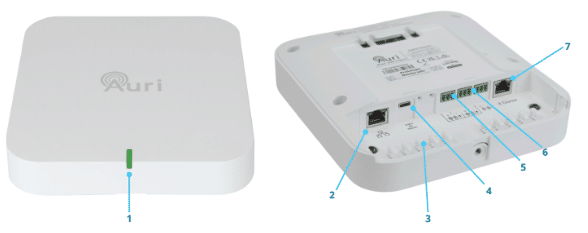
Unpacking
Unpack all contents from the box:
1x AURI-TX2N or AURI-TX2N-D Transmitter
1x Universal mounting bracket
3x Euroblock connectors
1x 1.8 m (6 ft) Cat6 cable
1x Quick Start Guide and Safety Data Sheet
Installation
Requirements
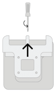
A Phillips head screwdriver is required for the captive retaining screw on the mounting bracket.
Fixtures and fittings such as electrical back boxes, screws and wall plugs will be needed, dependant on the install location.
A power supply is not included, if PoE is not available then a USB-C supply capable of delivering at least 500mA will be required.
Initial Setup
Remove the mounting bracket from the Transmitter, to do this you may need to loosen the retaining screw, then firmly slide the bracket away from the Transmitter.
Before installation it is recommended to do some basic setup of the Transmitter to ensure it is operating as required.
By default, the Transmitter will be set with both inputs at line level, with nominal gain and AGC disabled. The two inputs will be summed into a single 24 kHz mono broadcast, named “Auri [serial]-1”.
Apply power (USB-C or PoE), plug a line level audio source in to one of the inputs and confirm that the broadcast can be picked up by an Auri Receiver or Auracast enabled device.
Locating the Transmitter
Determine a suitable installation location for the Auri Transmitter. This should be chosen to ensure good coverage of the intended listening area for a range of different receiving devices.
See US Auri Coverage and Installation Guide.
See Rest of World Auri Coverage and Installation Guide.
Transmitters should be installed at a height above 6 feet (1.8 meters) on a wall or ceiling and the Auri logo must always be facing towards the intended coverage area.
When multiple Transmitters are used for larger coverage areas they should be spaced with an overlap of approximately 20% on the coverage for the least sensitive receiving device that is to be used in the space. See Commisioning Tools section for more information.
The Transmitter range will be affected by the sensitivity of the receiving device, different building environments and the density of other devices operating in the same frequency band. In larger or more complex spaces it is advisable to carry out an RF coverage design and site test to confirm best placement and number of transmitters needed for full coverage. Further details can be found in the Commissioning Tools section.
Range will be decreased when Receivers are covered or obstructed, for instance a single earbud or hearing aid will have much greater range with line of sight to the Transmitter, for this reason in larger spaces at least two Transmitters placed appropriately will provide much greater range and consistency of coverage.
Cabling
Once the install location has been determined, make sure there is a cable route established and run the required cables. As a minimum power (USB-C or PoE) and at least one source of audio (balanced mic/line or Dante) are required. A permanent network connection is recommended for configuration and ongoing management.
Installing the Bracket
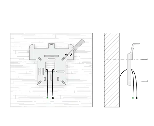
The mounting bracket supports a range of standard UK, EU and US electrical boxes, VESA 75 or direct mounting to a wall or ceiling. A minimum of two screws should be used to secure the bracket.
Rear or top cable entry is possible, depending on your install location.
Note that the bracket must be installed such that the Transmitter is facing into the room as coverage to the rear of the Transmitter is much lower.
With the bracket installed and cables terminated, hold the Transmitter close to the bracket and plug in the cables, a set of cable tie posts are provided to secure cabling and add strain relief.
Align the Transmitter below the bracket and push it upwards until you hear a click. The cable tray cover should be located in small slots at either corner.
Tighten the retaining screw at the top of the bracket.
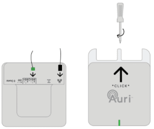
Configuring the Transmitter
With the final audio sources being connected, ensure there are signals representative of the intended use of the Transmitter, such as someone speaking into a microphone, or AV content being played.
As a minimum it is recommended to review the audio input mode and levels and to rename the broadcast, the Auri Manager software is required for configuration of the Transmitter. See the Auri Manager section of the handbook, and “Minimum Transmitter Setup” for more information.
The Transmitter output power should be adjusted to suit the install environment, in smaller spaces the Transmit Power should be reduced to avoid excessive signal being broadcast into adjacent areas. Where there are lots of Auracast systems operating in close proximity careful management of output power will result in better performance and a cleaner experience for the end users. Coverage should be validated in normal use of the space to ensure the Transmit Power is set appropriately for when the space is fully occupied.
Positioning Transmitters in Close Proximity
In some venues, there may be a need to use 2 or more transmitters to cover the same area with multiple channels. If this is required, then the transmitters should be positioned at least 30 cm (1 ft) apart to prevent any unwanted interactions.
LED States
|
State |
Meaning |
|
Solid Green |
OK |
|
Flashing between Green and Red |
Firmware update in progress |
|
Green, Blue, Red then Flashing Yellow |
Boot sequence |
|
Solid Yellow |
|
|
Solid Red |
System error – check status in Auri Manager, power cycle Transmitter or contact support |
|
Flashing White |
Identify |
|
Red, Off, Green, Off, Blue, Off |
Critical error, contact support |
Restart/Factory Reset
Two recessed buttons are located between the USB-C socket and mic/line input 1.
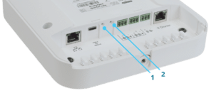
- Factory reset. The device can be reset through the Auri Manager software, however if it cannot be accessed through the software, for example due to incorrect network configuration or forgotten credentials then it can be reset by holding this button for 5 seconds or more. As soon as the status LED goes off the button can be released, the Transmitter will come back online with default settings restored.
- Restart. The device can be restarted through the Auri Manager software, however if it cannot be accessed through the software then it can be reset with a momentary press of this button. Note that this will not change any settings, it is the equivalent of turning the Transmitter off and on again.
Technical Specifications
|
Inputs |
|
|
Input selection |
2x audio inputs individually selectable between mic, line or optional Dante modes |
|
Mic/Line Inputs |
|
|
Connection |
2x 3-way 3.5mm pitch Euroblock (Balanced Inputs) |
|
Input impedance |
15kΩ |
|
THD+N |
0.03% at 0dBu (line mode) 0.02% at –25dBu (mic mode) |
|
Common mode rejection |
56dB |
|
Microphone Mode |
|
|
Max level before clipping |
-25 dBu |
|
Sensitivity |
-65 dBu |
|
Switchable phantom power |
+24 V |
|
Line Mode |
|
|
Max level before clipping |
+16 dBu |
|
Sensitivity |
-25 dBu |
|
Dante (optional) |
|
|
Connection |
Dedicated RJ45 socket |
|
Port speed |
100 Mbit |
|
Channels |
2 |
|
Sample rate |
48 kHz |
|
Outputs |
|
|
Line Output |
|
|
Connection |
1x 3-way 2.5mm pitch Euroblock (Balanced) |
|
Nominal output level |
+1 dBu |
|
Output impedance |
150 Ω |
|
Radio |
|
|
Bluetooth version |
5.3 |
|
Operating Frequency |
2400 to 2482 MHz |
|
Operating mode |
Auracast™ Compliant, Broadcast Only |
|
Supported codec |
LC3 |
|
Maximum output power |
North America: +20 dBm Rest of World: +10 dBm |
|
Output power control |
Attenuation from regional max to -10 dBm |
|
Encryption |
AES128-CCM encryption, with 4-16 character Privacy Keys |
|
Supported formats |
Mono or Stereo |
|
Network Audio |
|
|
Input routing |
Additional input source for each audio stream, must be selected from another TX2N on same network |
|
Connection |
Shared RJ45 with control and PoE |
|
Channels |
2x inputs 2x stereo outputs |
|
Format |
Multicast RTP |
|
Bit depth |
16 bit |
|
Sample rate |
16 kHz, 24 kHz or 48 kHz, matched to broadcast |
|
Bandwidth |
0.5 Mbit/s (16 kHz) to 1.5M bit/s (48 kHz) per stereo stream |
|
Latency |
5 ms nominal |
|
Audio Processing |
|
|
Input routing |
Disabled, Input 1 Only, Input 2 Only, Input 1 & 2 Stereo Pair, Input 1 & 2 Mono Sum |
|
AGC |
Switchable, 20 dB gain control range |
|
Low cut |
Switchable, 24 dB/oct, frequency based on sample rate 16 kHz sample rate: 75 Hz 24 kHz sample rate: 110 Hz 48 kHz sample rate: 220 Hz |
|
Sample rates |
16 kHz, 24 kHz (Auracast Standard – required) 48 kHz (Auracast High) |
|
Frequency response +/- 3 dB (internal, line in to line out) |
16 kHz sample rate: 50 Hz – 7.5 kHz 24 kHz sample rate: 50 Hz – 11.0 kHz 48 kHz sample rate: 50 Hz – 22.5 kHz |
|
Latency (internal, line in to line out) |
13ms |
|
Latency (complete system, end to end) |
Auri RX1 – 29 ms to 45 ms (dependant on sample rate and mono/stereo) Other receivers will vary |
|
Network |
|
|
Port speed |
100 Mbit |
|
IP address |
DHCP, static or link-local |
|
Protocols |
mDNS, UDP (unicast), RTP (multicast), RTCP (multicast) |
|
Security |
UDP communication AES256-GCM |
|
Controls and Indication |
|
|
Buttons |
Recessed restart and factory reset buttons |
|
Setup/Programming |
Via Auri Manager Software |
|
Status LED |
RGB multi-function LED, see handbook for states |
|
Power |
|
|
PoE |
IEEE 802.3af |
|
USB-C |
5V PD Compliant |
|
Power consumption (nominal) |
USB-C: 5 V, 370 mA (1.85 W) PoE: 48 V, 53 mA (2.54 W) |
|
Physical |
|
|
Dimensions |
183 x 173 x 48 mm (7.20 x 6.81 x 1.89 in.) |
|
Weight |
TX2N – 0.45 kg (0.99 lbs.) TX2N-D – 0.47 kg (1.04 lbs.) |
|
Shipping Weight |
TX2N – 1.03 kg (2.27 lbs.) TX2N-D – 1.05 kg (2.31 lbs.) |
|
Enclosure Material |
PC-ABS |
|
Colour |
White |
|
Mounting |
Removable wall/ceiling bracket Multiple holes to support mounting on standard UK, EU and US electrical back boxes and VESA 75 |
|
Environmental |
|
|
Temperature – Storage |
-40 °C (-40 °F) to 70 °C (+158 °F) |
|
Temperature – Operation |
-10 °C (14 °F) to 40 °C (+104 °F) |
|
Relative Humidity |
0 to 95% relative humidity, non-condensing |
|
IP Rating |
IP30 (with mounting bracket attached) |
|
Compliance |
|
|
Standards |
FCC, ISED, CE, UKCA, RCM, MIC-R, RoHS, REACH, WEEE |
|
Specifications are subject to change without notice |
|
Receivers (AURI-RX1)
The Auri Audio Receiver is a state-of-the-art assistive listening Receiver, allowing venues to provide hearing assistance to guests while meeting compliance with disability and accessibility requirements.
Unpacking
Unpack all contents from the box:
1x AURI-RX1 Receiver
1x Quick Start Guide and Safety Data Sheet
First Use
Remove the protective screen cover. The Receiver will not activate until charged, connect a USB-C power supply or insert in a Docking Station and fully charge before use. The Receiver LED will flash white while charging and be solid white at full charge.
Note that the Dock is required to charge the RX1, plus connection to the network is required for configuration and firmware updates via Auri Manager.
General Operation
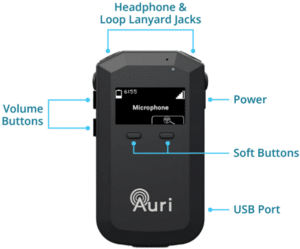
- Press and hold the Power button for 1 second to turn Receiver on. The Receiver will turn on automatically when removed from the Docking Station, or when USB power is unplugged.
- The Receiver will scan for available Auri broadcasts, when there is a single broadcast the RX1 will connect to that broadcast automatically. If more than one broadcast is available then the RX1 will list the available broadcasts in order of strongest signal. In the event of no broadcasts being found, this will be indicated on screen by way of a no signal symbol.
- Plug headphones, ear speaker, earbuds or compatible neck loop into the headphone and loop lanyard jacks.
- Activate the display by a momentary press of the power or either of the front buttons.
- Press the front right “scan / select” button to look for other broadcasts, these will be presented in a list which can be scrolled using the front left button or by the volume up and down buttons. Use the “scan / select” button again to connect to the highlighted broadcast.
- Adjust volume by pressing volume up and down buttons.
- To power down, press and hold the Power button for 3 seconds.
Display
The status screen shows a range of information about the Receiver and current connection.
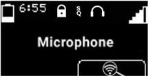

|
Indicates battery level and approximate remaining battery life in hours. |

|
Shows when connected to an encrypted broadcast. |
|
|
Indicates broadcast quality (sample rate). SQ is shown when connected to a Auracast compliant 16 kHz or 24 kHz broadcast, HQ is shown for high quality 48 kHz connections. |
|
|
Displays whether the Receiver is currently connected to headphones or to a neck loop lanyard. |

|
Indicates current signal strength, a flashing line through this icon represents no connection. |

|
The name of the currently connected broadcast. If there is no connection this will indicate the broadcast that the Receiver is trying to connect to. |

|
Scan icon, pressing the soft button below this will initiate a new scan. |


When navigating a list or menu the icons above the soft buttons will change to represent the button function.
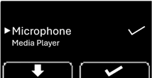

|
Scroll down a list, used when selecting from available broadcasts. |

|
Select, press to choose the active list item. |

|
Back, steps one level back up the menu structure. |

|
The arrow indicates the currently selected option in the list, this is also represented by a larger font size. |

|
The tick mark indicates the currently active option. |
Common Operations
Power / Status Button
A 1 second press of the Power button will turn on the Receiver.
Once the Receiver is on a short press of the Power button shows the status screen, this includes when any other screen such as volume, list or menu is showing in which case the Power button exits the current menu or screen.
When the status screen is active a short press of the Power button turns the screen off.
A 3 second press of the Power button turns the Receiver off, wait until the power icon is shown on screen then release the button.
Adjusting Volume
Pressing the volume controls from the status screen or with the screen off will adjust the volume in increments of 5%. Pressing and holding either volume button will continue to increase or decrease the volume in regular steps.
If no audio is currently available on the receiver a beep tone will be output with each volume change to give a representation of the new volume level.
Accessing the Menu
Press and hold Power and Volume Down for 2 seconds to access the menu.
Activating Scan Lock
Press and hold the Scan / Select button for 10 seconds, until the scan icon disappears to enable scan lock. Repeat the process until the scan icon is shown again to scan channel lock.
Battery Replacement
The Receiver battery must only be replaced with a genuine Auri LA-367 replacement battery. Loosen the screw in the rear of the Receiver, slide down and remove the battery door. Unplug the battery connector from the Receiver and dispose of the battery according to local regulations. Connect the new battery to the Receiver, refit the battery door and tighten the screw.
Receiver Settings
The Receiver has a range of optional settings that affect how it operates and the preferred behaviour when scanning and selecting available broadcasts.
To configure these settings the Receiver must either be in a compatible Auri D4 or D16 Docking Station and connected to the Auri Manager software, or they can be configured via the RX1 Menu.
To configure the Receiver via Auri Manager, see Portables section in this manual.
Configuring the receiver via the Rx1 Menu is easy to do. Press and hold the power and volume down buttons together for > 2 seconds.
The User Menu will become visible, navigation is by way of the volume up and down buttons to scroll, the left side soft button to go back and the right-side soft button to enter selection.
Auri Only
Enabled (default) – will only scan for broadcasts from Auri Transmitters and display them in the broadcast list, regardless of other settings.
Disabled – will scan for broadcasts from Auri and other 3rd party Auracast Transmitters, and display them in the broadcast list. Note: Library Lock and Scan Lock settings need to be disabled for 3rd party broadcasts to be listed.
Library Lock
Enabled – the Receiver will only display and connect to broadcasts which have been pre-programmed into its library via the Docking Station and Auri Manager
Disabled (default) – the Receiver will list any broadcasts within range which match other criteria.
Scan Lock
Enabled – the scan button cannot be used and is hidden on the Receiver display.
Disabled (default)—The scan button can be used as normal to find and connect to alternative broadcasts. When the Receiver is turned on, it will scan and connect to broadcasts based on the state of the other connection options.
Auto Connect
Off – when the Receiver is turned on it will scan and present a list of available broadcasts for the user to select from.
Strongest Broadcast – when powering on, this will cause the Receiver to automatically connect to the strongest available broadcast.
Previous Broadcast (default)– when powering on the Receiver will try to connect to the broadcast it was connected to prior to being turned off. If it cannot find that broadcast, it will keep scanning for it until the Auto Off time expires or the user scans and selects an alternative broadcast.
Auto Power
Enabled (default) – the Receiver will automatically turn off and charge when power is applied via the Docking Station or USB-C and automatically turn on when power is removed.
Disabled – the Receiver must be turned on/off manually, this means it will stay connected and outputting audio when placed in the Docking Station or when USB-C is connected.
Auto Off
30 Minutes (default) – the Receiver will automatically turn off after 30 minutes unless connected to a broadcast.
20 Minutes or 10 Minutes – turns off after 20 or 10 minutes without a connection.
Off – disables the Auto Off feature.
Jack Sense
Enabled (default) – the Receiver will turn on when headphones or a neckloop are connected to either of the 3.5mm ports and turn off after 1 minute when both ports are disconnected.
Disabled – the Receiver must be turned on/off manually.
Display Brightness
Auto (default) – uses the light sensor above the Receiver display to automatically adjust display between bright and dim modes based on ambient light.
Bright – display is set to full brightness.
Dim – display is set to low brightness.
Off – display is set to low brightness and does not activate when adjusting volume.
Default Volume
Sets the volume level the Receiver will be set to when it is powered on. Default is 35%.
Commissioning Tools
Within the RX1 Menu there is a Commissioning heading. The commissioning tools have two purposes, but both are designed to provide a smiple way of confirming that the Auri transmission is suitably positioned for the venue and the signal quality is adequate across the venue.
TX Survey
Provides a guide of general coverage across a venue simply by powering on a transmitter, so no need to connect audio, connect to a broadcast or install, simply position and carry out a site walk for an indication of the RSSI and if the coverage will result in good signal integrity with the transmitter placement.
Signal Quality
Provides a measure of the signal quality for a given selected broadcast. The user will need to select a broadcast channel for this tool to correctly function, and it is assumed the transmitter has been installed and audio is connected. The user can carry out a site walk and the signal level meter will indicate the quality level, which has three regions, Good, Fair, and Poor. It also includes a measure of interference which can indicate if the venue is suffering from Wi-Fi or other signal interference. This is noted as a wireless symbol with an exclamation mark through it.
More details on the tools and how to use them can be found in our Commissioning Tools Guide.
LED States
|
State |
Meaning |
|
Flashing White |
Charging |
|
Solid White |
Fully charged |
|
Slow Flashing Red |
Firmware update in progress |
|
Fast Flashing Red |
Battery error |
Technical Specifications
|
Audio |
|
|
Audio Output |
|
|
Connection |
2x 3.5 mm connections for wired headphones or inductive neck loops, supports TRS headphones |
|
Nominal Output Level |
0 dBu, 16 mW maximum |
|
Impedance |
32 Ω |
|
Audio Processing |
|
|
Frequency Response +/- 3 dB (system) |
16 kHz sample rate: 50 Hz – 7.5 kHz 24 kHz sample rate: 50 Hz – 11.0 kHz 48 kHz sample rate: 50 Hz – 19.5 kHz |
|
THD+N (system) |
< 0.5% Total Harmonic Distortion (at nominal level) |
|
Signal to Noise Ratio (system) |
> 60 dB (at nominal level) |
|
Latency (system) |
Auri RX1 – 29 ms to 45 ms (dependant on sample rate and mono/stereo) Other transmitters will vary |
|
Radio |
|
|
Bluetooth version |
5.3 |
|
Operating Frequency |
2400 to 2482 MHz |
|
Operating Mode |
Auracast™ Compliant, Broadcast Receive Only |
|
Supported Codec |
LC3 |
|
Encryption |
AES128-CCM encryption, with 4-16 character Privacy Keys |
|
Supported Formats |
Mono or Stereo |
|
Controls |
|
|
Buttons |
Power, Volume Up/Down, Two Front Multifunction Soft Buttons |
|
User Control |
Power on/off, display on/off, broadcast selection, volume up/down |
|
Setup/Programming |
Via Auri Manager Software/Docking Station |
|
Indicators |
|
|
Display |
31 x 16 mm (1.22 x .63 in), 64 x 128 pixel OLED display |
|
Display contents |
Broadcast playing, available broadcasts, battery level with time remaining, signal strength, volume status, charging status |
|
Light Sensor |
Visible light, automatically adjusts display brightness |
|
Status LED |
RGB multi-function LED, see handbook for states |
|
Power and Charging |
|
|
Power Supply |
USB-C PD Compliant or Docking Station – 5 V, 500 mA |
|
Dock Connection |
4 contacts w/ magnetic latch for charging and programming via docking station |
|
Battery Type |
Lithium Polymer, rechargeable, field replaceable |
|
Battery Size |
3.7 Vdc, 730 mAh |
|
Battery Life |
> 20 hours |
|
Battery Charge Time |
Fully charged in < 4 hours (dead battery) |
|
Power Save Modes |
Auto Off – powers down on loss of audio (adjustable 0 – 30 minutes) |
|
Auto Power – powers down on charging and powers on when removed |
|
|
Jack Sense – powers down when jack is disconnected (1 min), powers on when jack inserted |
|
|
Physical |
|
|
Dimensions with Belt Clip |
90 x 54 x 23 mm (3.54 x 2.13 x 0.91 in.) |
|
Unit Dimensions |
90 x 52 x 16 mm (3.54 x 2.05 x 0.63 in.) |
|
Unit Weight |
0.07 kg (0.15 lbs.) |
|
Shipping Weight |
0.09 kg (0.20 lbs.) |
|
Enclosure material |
PC plastic (IR transparent) |
|
Colour |
Black, Chrome Volume Buttons |
|
Belt Clip |
Removable |
|
Battery Door |
Removable for battery replacement |
|
Environmental |
|
|
Temperature – Storage |
-40 °C (-40 °F) to 70 °C (+158 °F) |
|
Temperature – Operation |
-10 °C (14 °F) to 40 °C (+104 °F) |
|
Relative Humidity |
0 to 95% relative humidity, non-condensing |
|
IP Rating |
IP40 |
|
Compliance |
|
|
Standards |
CE, UKCA, RCM, REACH, WEEE |
|
Specifications subject to change without notice |
|
Docking Stations (AURI-D4 / AURI-D16)
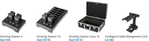
The Docking Stations allows for easy charging and management of Auri Receivers and are available in 4 or 16 unit options, with accessories such as the Docking Station case and intelligent cable management unit for the AURI-D16.
For a full description of features and configurations see the Auri Manager section of the handbook.
Unpacking
Unpack all contents from the box:
1x AURI-D4 or AURI-D16 Docking Station
1x LA-210 Power Supply
1x Quick Start Guide and Safety Data Sheet
Installation
Place the Docking Station on a flat surface or counter where Receivers are easily accessible.
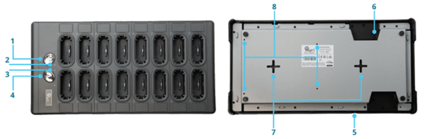
Alternatively, the Docking Station can be mounted to a wall or other surface using the wall mounting slots (AURI-D4 and AURI-D16). Mount two screws with ¼” heads 6 inches (150 mm) apart on a wall. Align the centre of the wall mounting slots over the screws and slide the Docking Station down to secure in place.
Connect the Docking Station to a power outlet using the provided power supply.
Connect the Docking Station to a Network, or to a PC for LinkLocal connection via an Ethernet cable, to enable configuration and control via the Auri Manager.
Insert your Auri Receivers into the charging pockets of the Docking Station. The Receiver(s) top status LED will begin flashing white to indicate the battery is charging and turn solid when fully charged.
LA-382 Intelligent Cable Management Unit
A cable management unit is available for conveniently storing headphones, ear speakers, neck loops, and other accessories (available for AURI-D16 only).
General Operation
Status Button
Press the status button to illuminate the displays of all Receivers and show status information.
Copy Button
A momentary press (0 – 2 seconds) will copy the library of broadcast names and encryption keys from the Docking Station to all docked Receivers, the red LED flashes slowly during this process.
A long press (2 – 5 seconds) will copy the broadcast names, encryption keys and Receiver configuration settings from the Docking Station to all docked Receivers, the red LED flashes quickly during this process.
Holding the button for longer than 5 seconds cancels the operation, the red LED will go off to indicate no action will be taken.
A settings cog animation will show on Receiver screens whenever settings are being transferred from the Docking Station.
LED States
|
State |
Meaning |
|
Off |
OK |
|
Flashing Red and Amber then flash Amber |
Boot sequence |
|
Flashing between Amber and Red |
Firmware update in progress |
|
Slow Flash Amber (1s) |
Identify |
|
Medium Flash Amber (0.25 – 0.5s) |
Updating |
|
Fast Flash Amber (0.1s) |
System warning – check status in Auri Manager and power cycle Docking Station |
|
Solid Amber |
System error – check status in Auri Manager, power cycle Docking Station or contact support |
|
Slow Flash Red (while holding left button) |
Ready to transfer broadcast library |
|
Fast Flash Red (while holding left button) |
Ready to transfer broadcast library and Receiver settings |
|
Alternating Red/Amber |
Critical error |
Restart/Factory Reset
Two recessed buttons are located opposite the RJ45 socket.
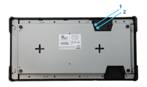
- Restart. The device can be restarted through the Auri Manager software, however if it cannot be accessed through the software then it can be reset with a momentary press of this button. Note that this will not change any settings, it is the equivalent of turning the Docking Station off and on again.
- Factory reset. The device can be reset through the Auri Manager software, however if it cannot be accessed through the software, for example due to incorrect network configuration or forgotten credentials then it can be reset by holding this button for 5 seconds or more. As soon as the status LED goes off the button can be released, the Docking Station will come back online with default settings restored.
Technical Specifications
|
Network |
|
|
Port speed |
100 Mbit |
|
IP address |
DHCP, static or link-local |
|
Protocols |
mDNS, UDP (unicast) |
|
Security |
UDP communication AES256-GCM |
|
Controls and Indication |
|
|
Buttons |
Copy and Status buttons Recessed restart and factory reset buttons |
|
Setup/Programming |
Via Auri Manager Software over network |
|
LEDs |
Copy LED (red) and Status LED (amber), see handbook for states |
|
Power |
|
|
Power Supply Input |
100-240 VAC, 50-60 Hz |
|
Power Supply Output |
12 VDC, 4.0 A, 48 W |
|
Power Supply Connector |
5.5 mm (.22 in.) OD x 2.3 mm (.09 in.) ID, barrel type |
|
Power Cable |
1.8 m (72 in.) Input Power Cable, 1.1 m (43 in.) Output Cable |
|
Physical |
|
|
Dimensions |
AURI-D4 – 50 x 192 x 150 mm (1.97 x 7.56 x 5.89 in.) AURI-D16 – 50 x 192 x 375 mm (1.97 x 7.56 x 14.77 in.) |
|
Unit Capacity |
4 or 16 Units |
|
Weight |
AURI-D4 – 0.65 kg (1.43 lbs.) AURI-D16 – 1.73 kg (3.81 lbs.) |
|
Shipping Weight |
AURI-D4 – 1.56 kg (3.44 lbs.) AURI-D16 – 2.79 kg (6.15 lbs.) |
|
Colour |
Black with chrome buttons |
|
Mounting |
Place on flat surface or use wall mounting slots |
|
Environmental |
|
|
Temperature – Storage |
-40 °C (-40 °F) to 70 °C (+158 °F) |
|
Temperature – Operation |
-10 °C (14 °F) to 40 °C (+104 °F) |
|
Relative Humidity |
0 to 95% relative humidity, non-condensing |
|
IP Rating |
IP20 |
|
Compliance |
|
|
Standards |
CE, UKCA, RCM, REACH, WEEE |
|
Specifications are subject to change without notice |
|
Auri Manager
The Auri Manager software allows discovery and configuration of all Auri Transmitters, docks and docked Receivers over the network.
It can be downloaded from the Microsoft store, search for “Auri Manager” or use this link Microsoft Store.
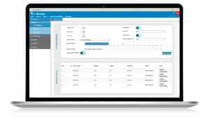
Auri Manager also can be requested from the website for those users who don’t have or are not able to use Microsoft Store services.
https://www.auriaudio.com/products/auri-manager-software/
Installation Requirements
The software should be installed on a Windows 11 PC with at least 300MB free space. With the addition of Auri Manager v1.6, Windows 10 is no longer supported.
The PC running the application must be connected to the same network as the devices to be controlled, and in the same subnet. A “link-local” setup is supported, where a single ethernet cable between the PC and the Transmitter or dock allows each device to automatically negotiate a compatible IP address with no wider network infrastructure or DHCP server needed.
Discovery uses mDNS and communication relies on UDP within the ephemeral port range, there must be no firewall settings in place that restrict this traffic.
The Auri Manager includes a new feature from v1.3 onwards which allows a user to manually input the IP addresses of each device in the event that mDNS has been disabled.
Network Requirements
|
Usage |
Type |
Address |
Port |
|
Device discovery |
mDNS (Multicast) |
224.0.0.251 |
5353 |
|
Control |
UDP (Unicast) |
Device IP (DHCP, Static or Link Local) |
55666, 56666 |
|
Firmware Update |
TFTP |
Device IP |
69 |
|
Network Audio |
RTP (Multicast) |
239.255.0.0/16 |
5004, 5006, 5008, 5012 |
|
Network Audio |
RTCP (Multicast) |
239.255.0.0/16 |
5005 |
Quick Start – Minimum Transmitter Setup
- Install the software.
- Connect a network cable between the PC and the Transmitter.
- Connect the intended audio inputs.
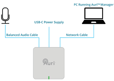
4. Power on the Transmitter (with PoE or USB-C).
5. Launch the software.
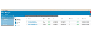
6. On the Devices page, identify the Transmitter you want to configure – this will be named “Auri-TX2N(-D)-SerialNumber”. If no Transmitter is shown, wait a short while, in a link-local configuration the Transmitter can take up to 2 minutes to obtain an IP address. New devices should be shown automatically, if not click the Refresh button to manually rescan. If the device still isn’t shown a firewall exception may be needed, see the Troubleshooting section for more information. A new device will be shown as an Auth state of “Default.”
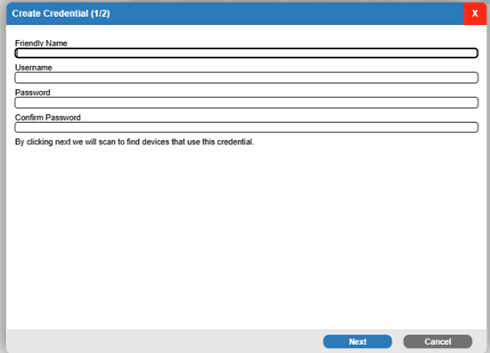
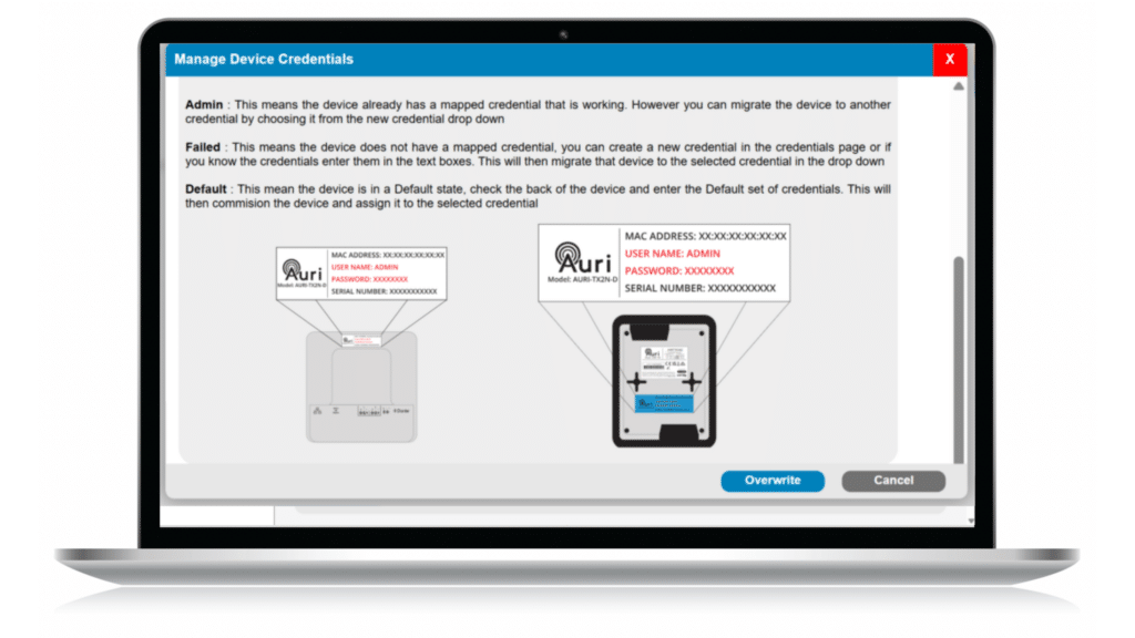
7. Click on the Transmitter name, in the dialog enter the username and password you would like to use to manage your devices, confirm the password and click Next.
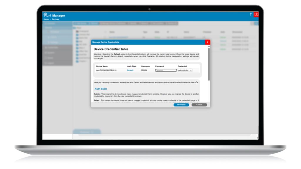
8. Enter the default password for your device, each device has a unique password, the defaults are printed on a label on the rear of the Transmitter.
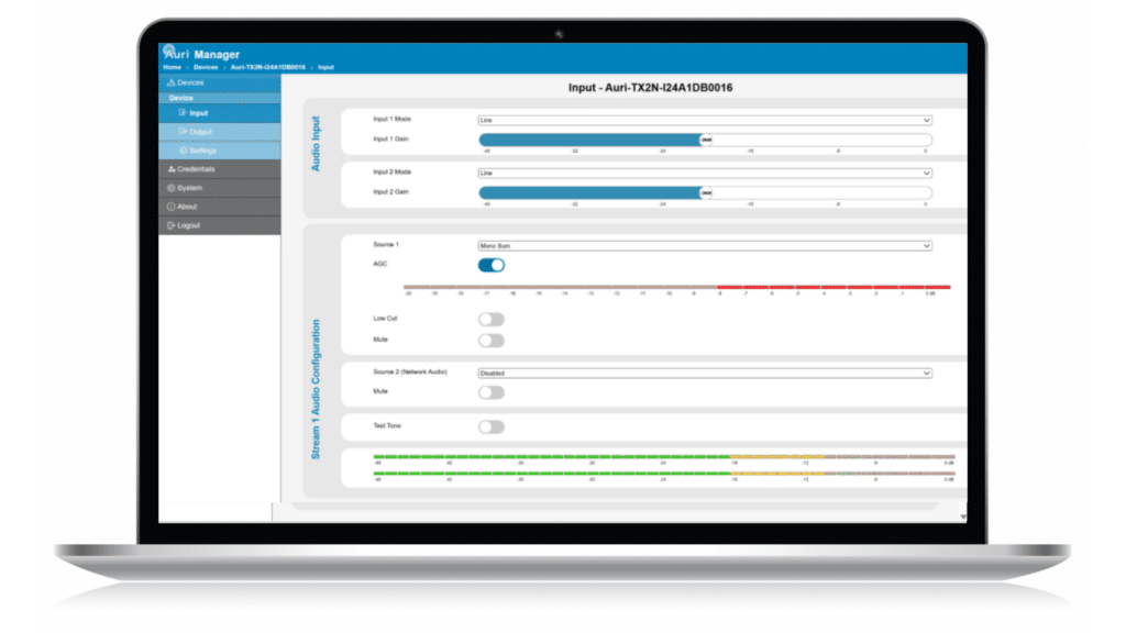
9. On the Inputs page, select the right microphone or line mode for each input and enable phantom power if needed.
10. With audio signals playing or someone speaking into the microphone, set a suitable input gain, such that the stream meters read around -18 dBfs.
11. If using a microphone directly into the Transmitter, consider enabling the Low Cut filter on the relevant stream, and AGC where input levels may be variable.
12. Navigate to the Outputs page and set Broadcast Name to something which users will be able to relate to the coverage area, for example the room name. Change Stream Name (Program Info) if desired.
13. Adjust encryption and sample rate settings as required.
14. If the second broadcast is being used, turn on the toggle switch to enable the radio and adjust the settings.
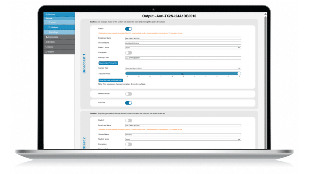
15. The Transmitter should now be broadcasting audio, connect a Receiver to confirm.
16. Adjust Transmit Power to the lowest level that provides full coverage of the intended area when the space is fully occupied.
System Setup
When first opening the application it will present a Devices list screen, with Devices and System tabs to the left. Once logged in an additional Credentials tab will be shown.
On the Devices page each online device name is a clickable link, when clicking a device link for the first time you will be presented with a Manage Device Credentials. If the device has already been configured with current user credentials, it will automatically bring up the Input Page for that device. If the device is in factory defaults you will first be asked to provide the default credentials which are printed on a label on the rear of the device.
Once authenticated with the first device, the software will automatically login to any other devices on the network which share the same credentials. Note that any device which the user has not provided the default credentials for will remain as Default Auth state and the user will not be able to access that device.
Note that there is no way to recover credentials once setup, other than a Factory Reset of the device. Ensure credentials are recorded in a secure place such as a password manager
Remember Me
When logging in a Remember Me checkbox is enabled by default. When ticked this securely stores the username and password used to authenticate with the devices. Next time the application is opened, the username and password shall be entered for the user and they can sign in.

Entering the correct password will allow the software to authenticate with all correctly authenticated online devices.
Authentication States
|
Application State |
Device State |
Auth Column |
Device Link Action |
|
Logged Out |
Factory defaults |
None |
Prompts for new credentials to be used, then prompts for device default credentials, then loads device page |
|
Logged Out |
Existing admin account |
None |
Prompts for username and password, then loads device page |
|
Logged In |
Correct credentials |
Admin |
Loads device page |
|
Logged In |
Factory defaults |
Default |
Prompts for device default credentials, sets up new admin account with current application credentials, then loads device page |
|
Logged In |
Incorrect credentials or unresponsive device |
Failed |
Prompts for device credentials, option to either switch account or overwrite the existing account with current application credentials, then loads device page |
Devices Page

The devices page provides a list of all Transmitters and Docking Stations which the software has been able to discover on the network. It also lists devices which have previously been discovered but are not currently online.
There is a toolbar along the top which supports some key device functions, the available buttons will depend on your authentication state, and which devices are currently selected.
The devices page can be toggled between the default table or a tile-based view, using the buttons on the right of the toolbar.
Status Monitor
The Status Monitor is a simple indication within the Device List which will indicate to users if there is a Warning or Error associated with any device.

A Warning will be highlighted with a Yellow Icon and an error will be indicated with a red icon. When the icon is clicked on, it will display a popup which will provide additional information about the nature of the issue.

Firmware Update
The section below describes the controls and features of Firmware, and the firmware update process.
Our start up Auri Manager now checks for new updates which may available. If an update is available, then the user will be notified and can make a decision what to do about it.
Auri Manager will check for devices which have outdated Firmware and label them with an icon in the device list for ease of identification. 

- Firmware – the tab in the bottom left of the software window opens a panel showing the available firmware packages. If no firmware has been downloaded yet then this will be blank, use the Download or Browse FW buttons to find available updates. When there are firmware updates available in this panel, one can be selected in order to apply it to online devices. Whenever a firmware package is selected the Devices list will be filtered to only show devices compatible with the selected firmware file. Click the Firmware tab again to close the panel.
- Download FW – automatically downloads available firmware packages from an online repository. The Firmware panel will be automatically opened at the start of this process, it may take a few seconds for firmware packages to start being added to the list.
- Browse FW – allows opening of firmware packages which have already been downloaded to a local storage location. Primarily used when Auri Manager is being used on a PC with no internet access. Once a firmware package has been opened the Firmware panel will be automatically opened.
- Update All Devices – A firmware package, and a minimum of one compatible device, which is online and authenticated, needs to be available to enable this button. Click on the Update All Devices button to transfer the firmware update package to all available devices and instigate the update.
- Update Selected Device(s) – a firmware package and at least one selected device from the device list needs to be available to enable this button. Click on “Update Selected Devices” to transfer the firmware update package to the selected devices in the device list and instigate the update.
- NOTE: The update will take around 10-15 minutes in total. The device status will be updated to show progress, and notifications will be provided at key points in the firmware update process.
Updating Firmware
Transmitters and Docking Stations

- Open the Firmware window at the bottom of the left side of the screen.
- Make sure the firmware package has been added to the application, using either the Download FW or Browse FW options.

- Next, select the firmware package to be installed. Selecting a firmware package by clicking on “Update All Devices” will automatically upload that file to all suitable devices in the device list.
- Alternatively select one or more devices to be updated in the device list, then click on the “Update Selected Devices” button to start the update for those selected devices only.
- Once initiated, the device state will show the following thee stages with a % complete for each stage. “Transferring,” “Extracting,” and “Updating,” this will take approximately 6 minutes on a Docking Station and 10 minutes on a transmitter.
- At the end of installation, the device will restart again and be rediscovered by the application. Confirm the firmware version has been updated as expected.
- If the update fails for any reason, restart the device and try again. If it fails repeatedly, contact support.
- NOTE: The software must remain open and connected to the device until at least the “updated” stage has started. If it is disconnected at any point before then, the update will fail. The devices must stay powered on until the entire update has been completed.
Receivers
Receiver firmware is included within the Docking Station firmware package.
- Ensure the Docking Station has been updated with the version to be installed on the receivers.
- By default, Docking Stations will be set to automatically update any receivers that are docked running an older version. In this mode, just dock the receiver and the update will start.
- To disable the automatic update function, go to the Docking Station Device page and turn off the “Auto Update Portables” toggle.
- To manually start a receiver firmware update, go to the Docking Station Portables page and click “Update All FW” at the top left of the screen. This will update all docked receivers.

- The receivers will show “Updating” in the status column with a percentage to indicate progress. The software can be closed while this is in progress.
- While a receiver is updating, the top LED will flash red. It should not be removed from the dock while this is happening. When the LED goes white again, the update is complete and the receiver can be removed.
- Receivers are updated in parallel, this means the update will take longer to complete if more receivers are docked when the update is started.
Add Device
Users can now, from Auri Manager v1.3, manually add a device to the Device List. This is particularly useful when mDNS is not possible due to venue network restrictions.

Enter the IPAddress of the device in the window as shown above and click “Search” if a valid device is found, it will be added to the table in the pop up window. Multiple devices can be added at one time.
Once all devices are found, the user can click the “Add” button, and the devices will be shown in the device listing page.
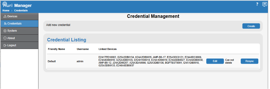
Manage Device Credentials
Credential management feature allows a user to expand the way they interact with devices. Here are some examples:
1. Single user: As a single administrator, you can create an account on your PC with a set of credentials then any device which you enter default credentials for, will take on the user login credentials you have used.
2. Single user multiple sites: As a single administrator, you again create an account on your PC with a set of credentials as above, you can assign devices to your login credentials for local on-site administration of devices, plus you can create one or more additional credential sets for another site. 
This is useful for users who may have responsibility across campuses or multiple sites and will enable them to apply different credential sets to groups of devices rather than having a single set across all devices.
Identify
Active only when one or more online and authenticated devices are selected. Identify flashes a white LED on the selected devices for 60 seconds. This helps confirm the right physical device is being selected before any further configuration and proves that network communication is working as expected.
Remove
Active only when one or more offline devices are selected. Allows offline devices to be removed from the list if these are not likely to be connected again.
Set Location
Active only when one or more online and authenticated devices are selected. Up to 4 levels of location hierarchy can be set to group devices when large numbers are available on the same network. For instance, in a university this may be used to segment devices by campus, building, floor and room.
Each input field will show a dropdown of existing locations at that level, which will be filtered as you type. These can be used to quickly prefill that location for the current device. To create a new location, click on the “Create New: location” option, or press the enter key. Existing locations are represented in blue, new locations are shown in green. Once all desired location levels have been set, click the Assign button. 
Locations are then represented by a folder tree in the left side of the device listing. Clicking on folders filters the list to only show devices grouped within that location and shows any further levels of location nested below.
To see all devices click on the “Root” folder at the top of the list.

Restart All
A recent addition to Auri Manger is the ability to restart all selected devices simultaneously instead of going to each one in turn, making more sense with larger installations. Either manually select a single, multiple devices or check the tick box next to “name” to select all online devices, then select “confirm.” 
Notifications

The management software supports notifications for certain events. Notifications can be accessed by clicking the icon in the top right corner, which is available from all pages within the application. The icon also shows the number of new, unread notifications.
New, unread notifications show the device name in bold to distinguish them from previously seen notifications.

Some notifications in the panel can be clicked to see more detail in a dialog window.
Each notification can be individually dismissed by clicking the X on the right of the notification.
All current notifications can be dismissed using the “CLEAR” button at the bottom of the panel.
Click the icon again or anywhere in the main window to dismiss the notification panel.
Help Icon
Each page has additional text to explain and support the user on how the functionality and features of that page are supposed to behave.
Click on the help icon  to open the help text and click anywhere on the page outside the help section or click the help icon again or click the X to reduce this again.
Transmitter Configuration
When accessing a Transmitter, you will initially be presented with an Input screen. There are two other pages for Output and Settings configuration.
Input

This page allows configuration of the physical mic/line or Dante inputs to the device, as well as choosing how these are routed to each of the two streams that the Transmitter supports.
Input Controls
- Input 1/2 Mode – this allows selection of microphone or line level input to set the right signal level. For Dante enabled devices a Dante option will also be available in this dropdown.
- Input 1/2 Phantom Power – enables +24V phantom power for the given input to support condenser microphones. This is only shown when the input is in microphone mode.

- Input 1/2 Gain – the sliders can be used to set the gain for each input, this is shown as a level relative to maximum gain (0dB) and provides an adjustment range of 40dB at 1dB intervals.
- When AGC is enabled the input gain control will only have an impact at -30 and -20dB thresholds, as the AGC will take control of the fine gain.
Stream Controls
The streams are the audio channels which are managed by the transmitter, these streams can be broadcast over Auracast, sent to the analogue line out or sent over network audio to other Transmitters.
- Source 1 – for each of the two streams this allows selection of whether the audio source will be taken from Input 1 Only, Input 2 Only, both inputs as a Mono Sum, both inputs treated as a Stereo Pair or the input Disabled.
- Setting a stream input to Stereo Pair will automatically set the Radio Output to Stereo.
- If either stream source is set as a stereo pair, the input modes, phantom power and input gain settings will be mirrored automatically between the two inputs and only a single set of input controls is shown.
- You cannot route Input 1 Only to Stream 2, or vice versa. Input 2 only to stream 1.
- AGC – allows a level of automatic gain control for the stream input. With this enabled the Transmitter will automatically adjust the input gains within a 20dB range to try and optimise the signal level. This is recommended when microphones are in use without any external dynamic control, as it helps avoid differences in volume between different talkers. When enabled an additional meter is shown to display the amount the AGC is reducing from full gain.
- When AGC is enabled the input gain control will only have an impact at -30 and -20dB thresholds, as the AGC will take control of the fine gain.
- Low Cut – enables a low-cut filter on the given stream input, to help with intelligibility when microphones are directly connected to the Transmitter inputs. Note that the low-cut filter knee frequency varies depending on the sample rate of the stream, see the Transmitter Technical Specifications for more information.
- Mute – mutes the audio input to the stream.
- Source 2 (Network Audio) – allows another Transmitter to be chosen as an input. The drop-down shows a list of all Transmitters which are online and have been enabled for Network Audio as an Output. Choosing a transmitter from the list will configure it as an audio source for the current transmitter to receive the audio stream. Each stream is handled independently so both streams will have to be enabled if the user needs both streams to be available across the network. This is primarily used when setting multiple transmitters as repeaters in larger installations.

- Mute – mutes the network audio input, if active.
- Test Tone – temporarily disables the audio inputs to the stream and plays a sinewave tone for verification of the system. The test tones of Stream 1 and Stream 2 are at different frequencies.
- Stream Meters – shows a live stereo signal level for the output of the given stream. The input gains or source audio levels should be adjusted to target the meters reading around the -18 dBFS level.
Output
 The outputs page is primarily for adjusting Auracast related settings, but also allows control of functions such as an analogue line output.
- Radio 1/2 – enables or disables the radio for each stream. If only one broadcast is in use, ensure the radio is disabled for the unused stream.
- Broadcast Name* – sets the name that users will see when scanning for an Auracast broadcast. A unique Broadcast Name should be provided for each output of each Transmitter. Unless the transmitters are being used as part of a larger group where the audio being transmitted is the same content. This would commonly be set to represent the room name for example. Supports 4-32 extended ASCII characters. We recommend 14 characters so the name is readable on the RX1 receiver. Greater than 14 characters will result in the name scrolling on the RX1 display.
- Stream Name – sets the “Program Info” field, which some broadcast assistants may show a user when selecting an Auracast broadcast or for more contextual information while listening. Auri Receivers do not display this field.
- Radio 1/2 Mode* – allows choice of whether the radio is broadcasting in mono or stereo. This is independent of the stream source, for instance it is possible to have mono source content and still have the radio set to broadcast stereo.
- Encryption* – selects between an open broadcast or a secure encrypted broadcast. When enabled a separate Privacy Key field is shown.
- Privacy Key* – when Encryption has been enabled, a 16-character privacy key is automatically generated. This information is needed for users to connect to an encrypted broadcast. Should be 4-16 extended ASCII characters. Note that if encryption is enabled but no privacy code is set, the broadcast will be openly available. Clicking the Regenerate Privacy Key button will refresh the Privacy Key with a new randomly generated key.
- View QR Code for Broadcast – allows the user to display the QR code for the selected broadcast. This can be scanned with a smartphone which supports QR code read function to connect to an Auracast-compliant receiver.

The QR code can be downloaded so a user can print and display the code for users to connect to a secure broadcast. - Sample Rate* – selects from 16 kHz, 24 kHz or 48 kHz sample rate, which affects the audio quality and useful frequency range of the broadcast. To be Auracast compliant as a venue, at least one radio must be broadcasting at 16 kHz or 24 kHz. Devices such as hearing aids are unlikely to support 48 kHz.
- Transmit Power* – allows adjustment of the radio output power to reduce range when covering smaller areas. Expressed as a dBFS level relative to maximum output power.
- Network Audio – enables or disables output of the stream to the network, used to send audio to repeaters. This will automatically be enabled if the Transmitter is selected as an audio input source for another Transmitter.
- Line Out – enables or disables a balanced analogue line output which is available only on stream 1. This will be a mono sum of the stream 1 content.
* Changes to these settings will cause the radios to restart, this will lead to a short loss of audio. Auri Receivers will automatically reconnect when the broadcast becomes available again, however 3rd party receivers may need to be manually reconnected.
Setting and Using Encrypted Broadcasts with RX1 Receivers
By default the Transmitter is configured for open, unencrypted broadcasts. This is the recommended approach in public areas where ease of access for people using personal devices is most important. For more secure environments encryption can be enabled to limit who can connect to the broadcast.
- Navigate to the Transmitter in Auri Manager and click through to the Output page.
- For the broadcast to be encrypted, turn on the Encryption toggle. A random 16-character Privacy Key will be automatically generated; this Privacy Key may be changed by the user if desired and shall be between 4 to 16 extended ASCII characters.
- Make a note of the Privacy Key, this will need to be made available to any users who will connect with their own devices, for example it may need showing on signage within the coverage area.
- The Privacy Key can be changed at any time by clicking the Refresh Privacy Key button.
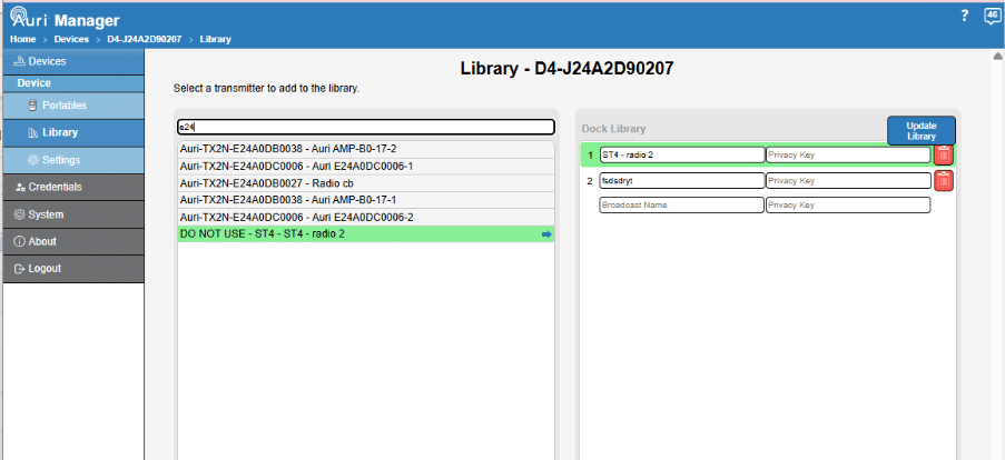
- Navigate to the Docking Station which is serving the area to be covered by the encrypted broadcast and click through to the Library page.
- In the left panel locate the broadcast that was configured in step 2, this will be referenced as “TransmitterName – BroadcastName” in the list.
- Click on the broadcast and confirm that it has been added to a spare row in the Dock Library within the right panel. This will store the Privacy Key in the dock and all currently docked Receivers.
- Remove a Receiver from the dock and confirm that it is able to list and connect to the broadcast. A padlock icon on the screen indicates connection to an encrypted broadcast.
- To ensure any Receivers docked in the future can access the broadcast, on the Portables page for the Docking Station set the Update Settings option to Auto Update Library. Alternatively, the left button on the Docking Station can be pressed to transfer the library to docked Receivers at any time.
Covering a Larger Venue
In scenarios where a single Transmitter cannot cover the required area, multiple Transmitters can be linked together, enabling broadcast of the same audio content.
Auri Receivers automatically connect to alternative Transmitters using the same broadcast settings. This means that if a user moves close to the edge of range from a Transmitter, if there is another transmitter with a stronger signal, the Receiver will automatically scan and if an alternative Transmitter is available it will reconnect to the second transmitter. It also means that when turning on a Receiver, if settings such as scan lock, library lock, or auto connect to previous are enabled, the Receiver will be able to connect to any Transmitter that matches the broadcast settings.
When performing a manual scan within range of multiple Transmitters using the same broadcast name, the Receiver will only show one of them in the list and connect to the one with the strongest signal.
Note that other third party Auracast receivers will show separate broadcasts with the same broadcast name and may not support automatic reconnection or roaming between Transmitters. Therefore, it may be that the user will have to reconnect manually to each transmitter.
There are two parts needed for a repeater configuration.
Audio Connections
Repeaters will need the same audio content to be connected to all Transmitters; this can be done in one of three ways:
- splitting the input audio signal
- Patching the same Dante output to all Transmitters
- Using the Auri network audio support.
We will consider Auri Network Audio option here.
To use network audio all Transmitters must be on the same network subnet. Network audio is sent as multicast RTP traffic, and it is strongly recommended to have IGMP configured properly if connecting to a wider network as without this multicast traffic will be treated as broadcast to all network hosts. This is not necessary if using Auri on a standalone, isolated network in which case a simple unmanaged switch can be used.
Start by making sure that a suitable audio source is connected to the primary Transmitter and that the input and stream settings are adjusted to give a suitable signal level. Connect to the broadcast and confirm everything works as expected with a single Transmitter.
In Auri Manager, follow these instructions to configure the system.
- Select the Primary Transmitter and open the “Output” page
- Enable Network Audio in Broadcast 1 / 2 or both if required
- Auri manager will request you to restart the transmitter – this is to establish a multicast IP address which will provide the Audio delivery onto the network – the primary transmitter is now configured
- Return to the devices list and select a transmitter which will be used as a repeater then open the “Input” page
- Within “Stream 1 Audio configuration” section find Source 2 (Network Audio) and open the pull-down menu.
- Select the Primary transmitter form the list (typically a single device will be listed in most cases) Auri Manager will ask for confirmation, and the device will restart (this is to configure the Multicast IP addresses.
- Now there will be 2 transmitters configured as a system broadcasting the same audio content over Broadcast 1. If Broadcast 2 is needed repeat steps 4 through 6 for the second broadcast, noting that the device does not need to be restarted again
- Adding additional transmitters to the Network Audio is simply a case of repeating steps 4 through 6 again for each transmitter needed as a repeater.
All Transmitters will be configured automatically for network audio, confirm that the audio level meters on the repeaters are showing similar signal levels to the primary Transmitter.
Broadcast Configuration
Certain Output settings should be matched between the Primary transmitter and each repeater to ensure that they work effectively together.
Settings from the Primary transmitter will automatically translate to the Secondary on activation of Network Audio with no user intervention.
The key settings are :
- Broadcast Name
- Radio mode (mono/stereo)
- Encryption state and Privacy Key if enabled
- Sample Rate
There may be cases where it is preferable to name the broadcasts differently, for instance where Transmitters are allocated to different sections of a theatre naming the broadcasts as “Stalls” and “Circle” could help users connect to the most appropriate Transmitter. Broadcast name can be changed manually post Network Audio configuration. Note that in this configuration the Auri Receiver will not be able to automatically connect to repeaters. If a user moved out of range and the repeater is named differently, the user would have to rescan and connect to the alternative Transmitter.
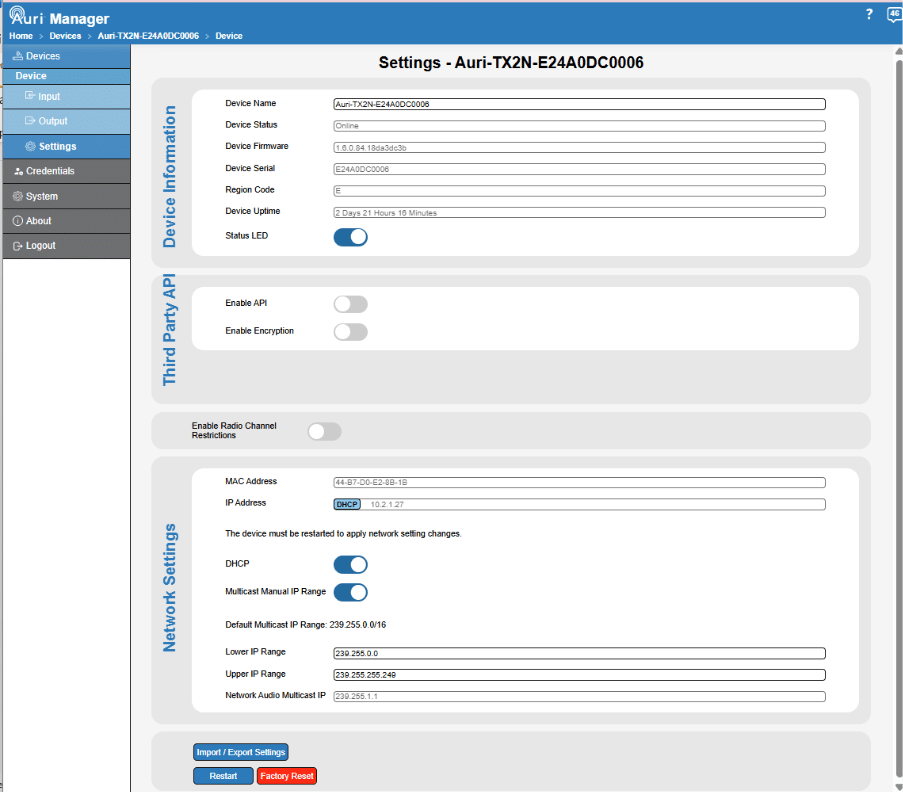
Settings

This page provides visibility and configuration of parameters relating to the Transmitter itself.
- Device Name – set the name the Transmitter will be known by in the device listing, notifications panel and other areas of the management software.
- Device Status – will report any errors or warnings related to the Transmitter.
- Device Firmware – reports the currently installed firmware version.
- Device Serial – the serial number of the Transmitter.
- Region Code – designates the radio region of the device.
- Device Uptime – the time that has passed since the Transmitter was last powered on or reset.
- Status LED – enables or disables the LED on the Transmitter so this can be turned off for installation in dark environments.
-
Third Party API – Enables the use of the third party API interface. This must be selected for each device which the user wishes to use within a separate control system. See below for more detail.
-
Enable Radio Channel Restrictions – allows a user to adjust the bandwidth of the radio. This in effect reduces the number of radio channels which the Auracast broadcast is transmitted over. A user may choose to enable this feature if interference has been detected and a particular Wi-Fi channel needs to be avoided for example.

- MAC Address – reports the MAC address of the Transmitter.
- IP Address – the current IP address and whether this was obtained from DHCP, Auto (link local) or static configuration.
- DHCP – enables or disables the DHCP Client on the Transmitter. When DHCP is enabled the Transmitter will wait 30 seconds for an address to be assigned by a DHCP server, after this the Transmitter will revert to an address in the link-local range (169.254.0.0/16)
- The following fields are only active when DHCP is disabled and are used to set static network configuration. Note: any changes to network settings are only applied when the device is next restarted. Take care when assigning static IP addresses, misconfiguration may make the device uncommunicable.
- Static IP Address
- Subnet Mask
- Gateway
- Primary DNS
- Secondary DNS
- Network Audio Multicast IP – is the IP address used for network audio streams between Transmitters. When setting up network audio streams the software will manage multicast addresses to ensure unique addresses are used for each group of transmitters. Users can also select to manually adjust the effective range for which the Multicast IP addresses can be set to.

- Import / Export Settings – allows you to import or export a configuration file for a device. See below for more details.
- Restart – restarts the Transmitter. This will not change any settings but will allow changes to network parameters to be applied.
- Factory Reset – this will restart the device with ALL settings reset to the default factory configuration, including username and password.
Third Party API
Introduction
Where available for the required control system being used, we recommend the use of provided
plugins. A Q-Sys plugin is available for download here Plus Approved plugins for Q-Sys and Crestron will be available by end of Q2 2026
Simple set and forget commands can generally be implemented very simply, parsing
responses may require more experience in scripting or development for the intended platform.
Overview
Support for the API was introduced in firmware version 1.5, alongside Auri Manager version
1.4 being required to enable the API. If you are running older versions, please update before
attempting to use the API.
The API is disabled by default and must be enabled via the Settings page of each device in
Auri Manager. 
The API is set to use plaintext UDP commands by default with no authentication to read and write data, so if enabling the API ensure that the security of the network is considered suitable to avoid misuse.
From v1.6 Auri Manager and v1.6 FW release the API can be used encrypted and the user has the option of two types of encryption which has been supported. This can be selected in the pull down in the Third Party API settings section of Auri Manager. 
If encryption is selected then the encryption key can be refreshed by clicking on the Refresh Key button. Or sending the appropriate command via the API.
A limited subset of commands are supported, primarily focused on monitoring device
status and managing broadcast security.
Each command sent will receive a response over the same UDP interface.
Key Information
You will need to know the IP address of the device before connecting, this can be found
through the Devices page on Auri Manager.
It is recommended to use a fixed IP to avoid the API connection being interrupted, either by
assigning a static IP address or reserving the address in the DHCP server.
You must ensure that UDP traffic over port 54666 is allowed between the Auri product and
the device intended to control it.

For more details around the API please refer to the following document.
UP3B615 Auri Third Party Control API – Customer Documentation.pdf
Which can be requested via our support team or downloaded directly from our website https://www.listentech.com/support/manuals/
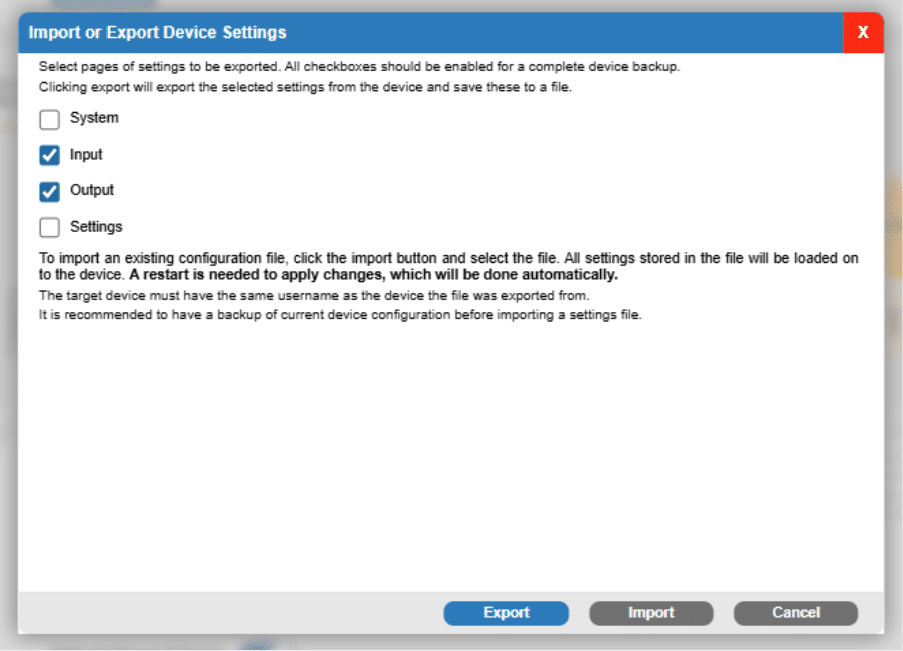
Import or Export Device Settings

Tick boxes allow selection of which parameters to be saved based on the software settings pages, the system tick box includes device location. Select all for a complete device backup.
Usernames and passwords are never stored in a configuration file.
On Export the settings will be stored in an encrypted .auri file, named after the device name, date and time of export and saved locally in My DocumentsAuri.
To import an existing settings file to a device you must first be authenticated with the same username as the device the file was exported from, then click Import and select the file. All settings stored in the file will be copied to the device regardless of which tick boxes are selected.
Dock Configuration
When accessing a dock, you will initially be presented with a Portables page. Library and Settings pages are also available.
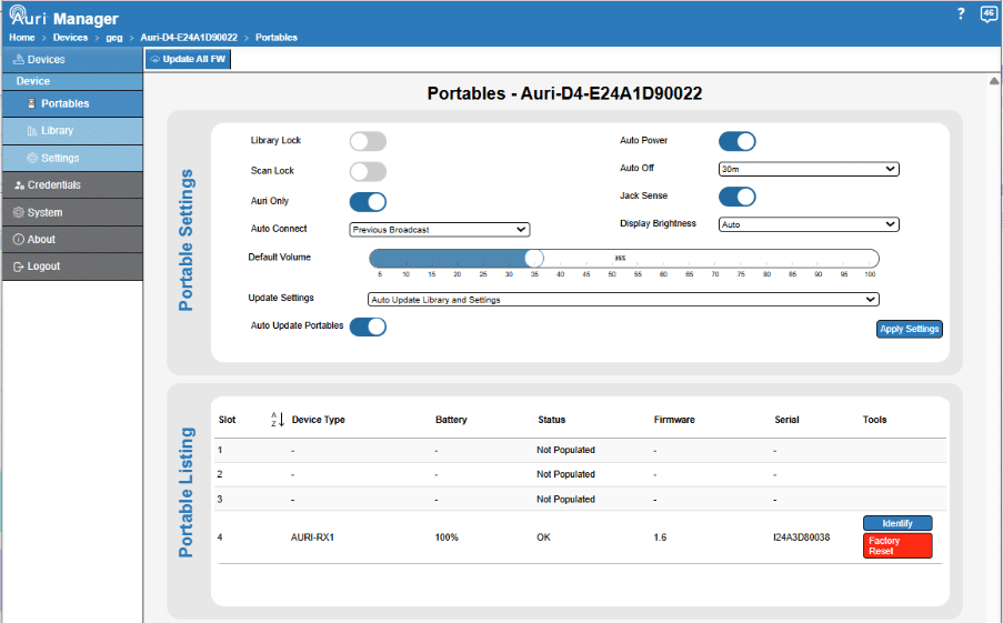
Portables

This page is primarily to view and configure Receivers currently within the dock.
Receiver Settings
Docking stations are able to store a full Receiver configuration, the current configuration stored on the dock is read back to the controls at the top of this page and can be adjusted as required. Any settings changes will be immediately applied to all currently docked Receivers.
For an overview of the Receiver settings, see the Receiver section of the handbook.
Update Settings
- Manual – Stored settings on the Docking Station will not be sent to newly docked Receivers automatically. Settings can be copied to all docked Receivers at any point by clicking the Apply Settings button. Library and settings can also be copied to the receiver using the left button of the Docking Station.
- Auto Update Library – The library of 32 broadcasts will be automatically sent to Receivers as soon as they are placed in the dock. This will overwrite existing Receiver libraries, and if the dock library is empty the Receiver library will be wiped when docked.
- Auto Update Settings – The Receiver settings stored on the dock will be automatically sent to Receivers as soon as they are placed in the dock, this will overwrite existing Receiver settings.
- Auto Update Library and Settings – Both the library and Receiver settings stored on the dock are automatically sent to Receivers upon being docked. . When library or settings are updated on docked Receivers, a spinning gear icon will be shown on screen.
/* Style Definitions */
table.MsoNormalTable
{mso-style-name:"Table Normal";
mso-tstyle-rowband-size:0;
mso-tstyle-colband-size:0;
mso-style-noshow:yes;
mso-style-priority:99;
mso-style-parent:"";
mso-padding-alt:0in 5.4pt 0in 5.4pt;
mso-para-margin:0in;
mso-pagination:widow-orphan;
font-size:12.0pt;
font-family:"Aptos",sans-serif;
mso-ascii-font-family:Aptos;
mso-ascii-theme-font:minor-latin;
mso-hansi-font-family:Aptos;
mso-hansi-theme-font:minor-latin;
mso-font-kerning:1.0pt;
mso-ligatures:standardcontextual;}
Auto Update Portables
When enabled the Docking Station will automatically update the firmware of any Receivers that are docked with an older firmware version current installed. When disabled the “Update All FW” button from the Portables page must be used to manually start an update for all docked Receivers.
A table is shown representing the number of slots in the Docking Station, when a Receiver is in any of the slots it will show in the corresponding table row, with the battery level, status, firmware version and serial number. There are also two buttons in each table row –
- Identify – turns on the screen of the Receiver to confirm the right physical device is being selected before any further configuration and proves that communication is working as expected.
- Factory Reset – resets the Receiver to factory default settings.
A single toolbar button is available –
- Update All FW – sends the firmware package stored on the Docking Station to all currently docked Receivers. See Updating Firmware for more information.
Library

The docks can store a library of up to 32 broadcast names and privacy keys if needed. This library can be set to either automatically update any Receivers as soon as they are inserted into the dock, or so that a button press is needed on the dock for a transfer to happen.
The library is provided so that Receivers can connect to encrypted broadcasts without having to manually enter a password. Additionally, it allows the Receiver to be locked down so that it will only connect to one or more pre-configured broadcasts via Library Lock.
This page allows each of the 32 library entries to be manually entered, or alternatively you can search and select from broadcasts available from any Transmitters currently on the network, to copy the broadcast name and privacy keys automatically into the dock library.
The right panel will load the current broadcast library from the active dock. Each of these rows can be manually edited or can be removed by clicking the bin icon on the right.
A new blank row will automatically be added as needed, until all 32 rows are used.
The left panel lists the broadcast names for all online and authenticated Transmitters, so these can be selected to add into the dock library. Click anywhere on a row to add it into the dock library, the row will then be shown in a darker grey to indicate it is already present in the library.
In larger systems the search bar can be used to help find the required Transmitters and broadcasts.
Settings
Matches the options available on the Transmitter Settings page, with the exception of controls mentioned below.
- Region Code, Status LED, Channel Restrictions, and Network Audio Multicast IP are not applicable to the Docking Station.
Credentials

The credential page can be used to update the username and password used to authenticate with devices. The base credential which has been created when setting up the login cannot be deleted. You can only delete all trace of Auri Manager by uninstalling form the machine and re-installing.
Note that changes on this page can only be applied to devices which are currently online and authenticated. It is recommended to ensure all devices are connected when a change is made to avoid some devices being left on old credentials.
Changes to the credential details will apply to ALL online authenticated devices.
- Edit – The edit credentials popup will show all current details for each of the online and authenticated users.
- The user can edit Friendly name, Username and select the option to change Password and the password hint. Note any changes will require the user to re-login using the new credentials.
Create – allows a user to create a new set of credentials for one or more online and authenticated devices.

Once a new credential has been created online and authenticated devices can be assigned to that credential via the Manage Device Credentials feature on the Devices page.
- Resync – simply refreshes the connection and ensures all devices have the most up to date credentials and settings.
Usernames can include alphanumeric characters plus period, hyphen and underscore. Passwords support all ASCII characters.
System

Software Application Update
The Auri Manager application can automatically check for updates once launched. Check this box to enable this feature.
The release notes for the latest and previous releases can be viewed by selecting the “View Release Notes” button.
Firmware Update
Auri Manager can automatically check for Firmware Updates, check the box to enable this feature. No firmware will be automatically updated; the user has full control over when updates are initiated.
Device Error Reporting
Auri Manager allows a user to be notified of certain information via email alert. Note this requires a dedicated SMTP server which is configured to send emails.
Device List Import/Export
Auri Manager will save the current and full device list to file so that it can be restored in the event of a user changing PC for example.
Theme Selection
Auri Manager supports both a light mode and a dark mode.
About
Displays contact information and the currently installed software version number.
Troubleshooting
No devices discovered in Auri Manager
Ensure devices have a network connection, are powered on and are on the same network subnet as the PC running Auri Manager.
If using link-local the devices will take around 2 minutes to obtain an IP address and be discovered.
Click the “Refresh” button
In most cases Auri Manager will request access to the network when first opened and permission should be granted, if no devices are being discovered then check the firewall settings; this is most commonly needed in link-local configurations.
In the Windows Start Menu search for “Allow an app through Windows Firewall”.
Click “Change settings” then scroll down the list to find “Auri Manager” and enable the checkboxes in all available columns.
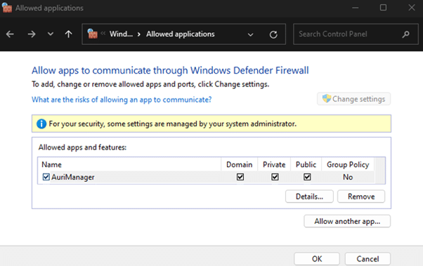
RX1 Receiver will not power on
Make sure the Auri RX1 Receiver has a fully charged battery or is connected to a standard USB charger. Make sure the power button on the right side of the unit has been pressed for 1 second to turn the unit on. If this does not work, make sure the battery is installed properly or install a replacement battery. If using the Receiver for the first time, fully charge it using a USB charger or Auri Docking Station before use.
Receiver cannot connect to broadcast
Make sure the Receiver is within range of the Transmitter. If the broadcast is encrypted, ensure the details have been stored in the Receiver library through Auri Manager and a network connected Docking Station. Ensure the Receiver does not have “Library Lock” enabled, if so make sure the broadcast is added to the Receiver library.
There is no audio
Firstly, make sure the Auri RX1 Receiver is connected to the correct broadcast. Make sure the Auri TX2N Transmitter is powered on and has an audio source connected. Review the Transmitter Input settings in the Auri Manager application, make sure the correct input mode is selected, the stream sources are configured correctly and adjust the input gain such that the stream meters read approximately -18 dBfs. Make sure there is a suitable headphone or neck loop connected to the Auri RX1 and that the volume is set to a suitable level.
Secondly, now we have released v1.4 Firmware, there is a Signal Quality tool which will also assist in determining if there is any unwanted interference in the radio domain. See section for Commissioning Tools.
Audio is distorted
Review input mode and input gain on the Transmitter in the Auri Manager application. Adjust settings such that the stream meters read approximately -18 dBfs. Verify that the source audio being sent to the Transmitter is clean and undistorted.
Device state shows Firmware Error in Auri Manager
A firmware error can be shown due to a failed update or a corrupted image on the device. In some cases this may mean the device is running a recovery image with limited functionality. First try restarting the device and see if the state recovers to Online when rediscovered by Auri Manager. If the device still shows a Firmware Error after restarting, try installing the latest available firmware package for that device. If the error persists or the firmware update fails contact support.
Device does not boot or continuously restarts
The Transmitters and Docking Stations can be restarted into a recovery image by holding down the factory reset button while power cycling the device. After this has been done the device will be on the original firmware release with all settings erased. Update the firmware to the most recent version and reapply settings as needed.
Accessories
A complete range of accessories is available to complement your Auri system.
Neck loops allow Receiver compatibility for users with telecoil equipped hearing aids and cochlear implants.
The Auri RX1 is compatible with standard 3.5mm headphones or earbuds, a range of options are available from your Auri dealer.
Other accessories include spare battery packs, one-port USB chargers, cases and signage.
For a full list of Auri accessories visit www.auriaudio.com
Compliance
FCC Regulation Statements:
FCC part 15 subpart C (FCC ID: 2BHN3TX2N)
FCC part 15 subpart B
This device complies with part 15 of the FCC Rules. Operation is subject to the following two conditions: (1) This device may not cause harmful interference, and (2) this device must accept any interference received, including interference that may cause undesired operation.
NOTE: This equipment has been tested and found to comply with the limits for a Class B digital device, pursuant to part 15 of the FCC Rules. These limits are designed to provide reasonable protection against harmful interference in a residential installation. This equipment generates, uses and can radiate radio frequency energy and, if not installed and used in accordance with the instructions, may cause harmful interference to radio communications. However, there is no guarantee that interference will not occur in a particular installation. If this equipment does cause harmful interference to radio or television reception, which can be determined by turning the equipment off and on, the user is encouraged to try to correct the interference by one or more of the following measures:
—Reorient or relocate the receiving antenna.
—Increase the separation between the equipment and Receiver.
—Connect the equipment into an outlet on a circuit different from that to which the Receiver is connected.
—Consult the dealer or an experienced radio/TV technician for help.
Any changes or modifications made to this device that are not expressly approved by Listen Technologies may void the user’s authority to operate the equipment.
The information in this guide may change without notice. The manufacturer assumes no responsibility for any errors that may appear in this guide.
ISED Regulation Statement:
ISED RSS-247 issue 3 (IC ID: 32898-TX2N)
CAN ICES-3 (B)/NMB-3 (B)
This device complies with Innovation, Science and Economic Development Canada’s licence-exempt RSS(s). Operation is subject to the following two conditions:
- This device may not cause interference.
- This device must accept any interference, including interference that may cause undesired operation of the device.
Cet appareil contient des émetteurs/récepteurs exempts de licence qui sont conformes aux RSS exemptés de licence d’Innovation, Sciences et Développement économique Canada. L’exploitation est soumise aux deux conditions suivantes:
- Cet appareil ne doit pas provoquer d’interférences.
- Cet appareil doit accepter toute interférence, y compris les interférences susceptibles de provoquer un fonctionnement indésirable de l’appareil.
For Users in the European Union
This device is a Bluetooth Low Energy system operating in the 2.4 GHz frequency band from 2.400 GHz to 2.482 GHz. The usage of this device is generally allowed in all EU countries, Australia, New Zealand, Singapore, and Hong Kong. Product labelling information such as serial number, manufacturer, and additional regulatory information is found on the product label on the device.
EU Declaration of Conformity
Hereby, Ampetronic and Listen Technologies declares that the radio equipment type AURI-TX2N, AURI-TX2N-D, AURI-D4, AURI-D16 and AURI-RX1 is in compliance with:
Radio Equipment Directive 2014/53/EU
ETSI EN 300328 V2.2.2
Electromagnetic Compatibility Directive 2014/30/EU
ETSI EN 301489-17 V3.2.4
EN 55032:2015+A1:2020
EN 55035:2017+A11:2020
EN 61000-3-2:2019+A1:2021
EN 61000-3-3:2013+A2:2021
Low Voltage Directive 2014/35/EU
EN62368-1:2020+A11:2020
RoHS 3 Directive EU 2015/863
REACH EC 1907/2006
WEEE Directive (2012/19/EU)
Battery Directive (2006/66/EC & 2013/56/EU)
If you wish to discard electrical and electronic equipment (EEE), please contact your dealer or supplier for further information.
The full text of the EU declaration of conformity is available at the following internet address: www.auriaudio.com
Japan
Radio Ordinance Article 2, paragraph 1, item 19 (MIC ID 205-240087)
Warranty
Ampetronic and Listen Technologies warrants the AURI-TX2N, AURI-TX2N-D, AURI-D4, AURI-D16 and AURI-RX1 to be free from defects in materials and workmanship under normal use and conditions for 5 Years from the original date of purchase.
Lithium polymer batteries supplied with receivers carry a one year limited warranty from date of purchase.
Related accessories such as headphones and neck loops carry a one year limited warranty from date of purchase.
For the current warranty conditions, please visit our website at www.auriaudio.com or contact your local dealer.
Contact Information
LISTEN TECHNOLOGIES 14912 Heritage Crest Way, Bluffdale, Utah 84065-4818 USA
Phone: +1.801.233.8992 Toll-Free: 1.800.330.0891 www.listentech.com
AMPETRONIC Unit 2, Trentside Business Village, Farndon Road, Newark, NG24 4XB, United Kingdom
Phone: +44 1636 610062 www.ampetronic.com
Copyright © 2026. All rights reserved.
Testing this out to see if the same issue arises.
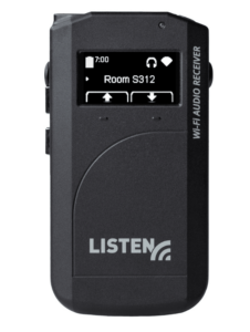
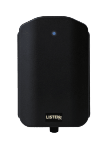
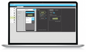
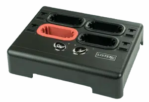
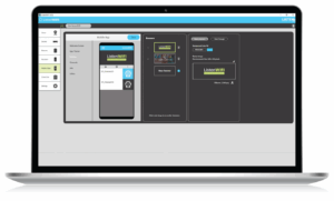

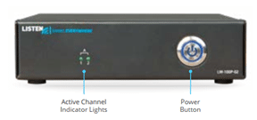
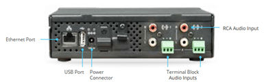
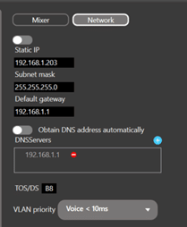

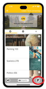
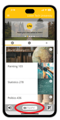

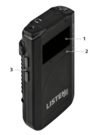
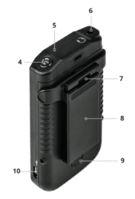
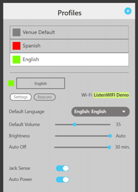
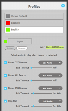
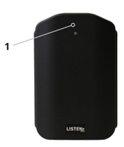
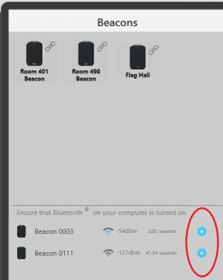
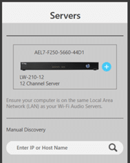

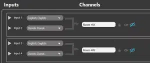
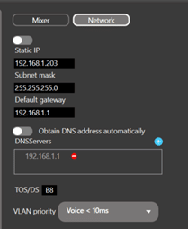
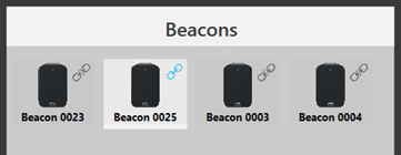
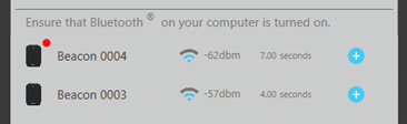
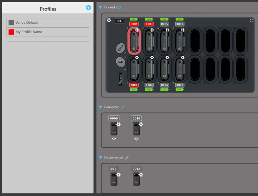
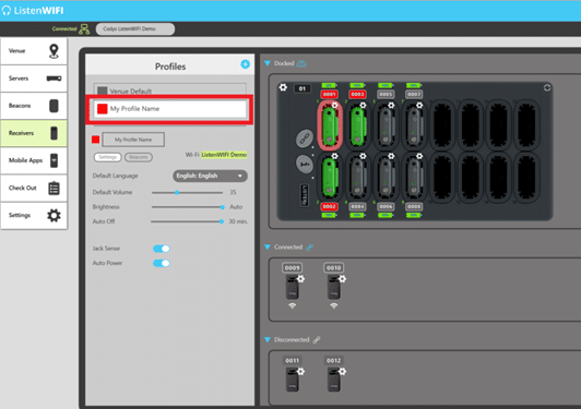
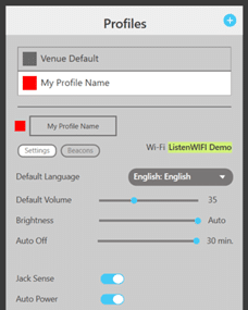
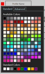
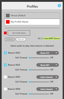
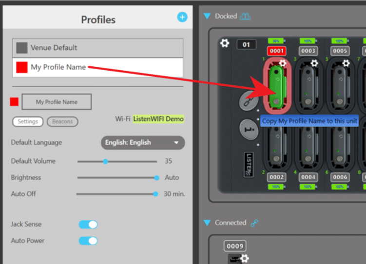
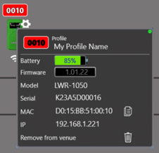
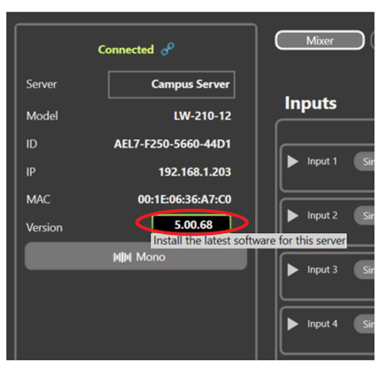
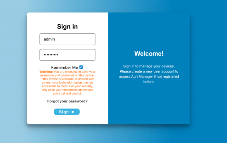

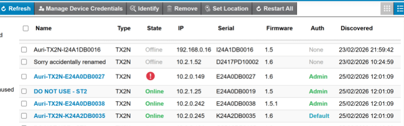
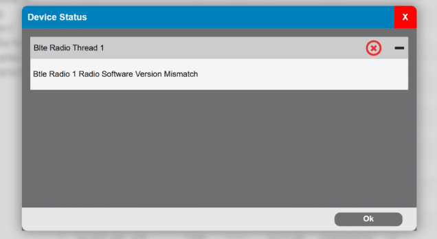

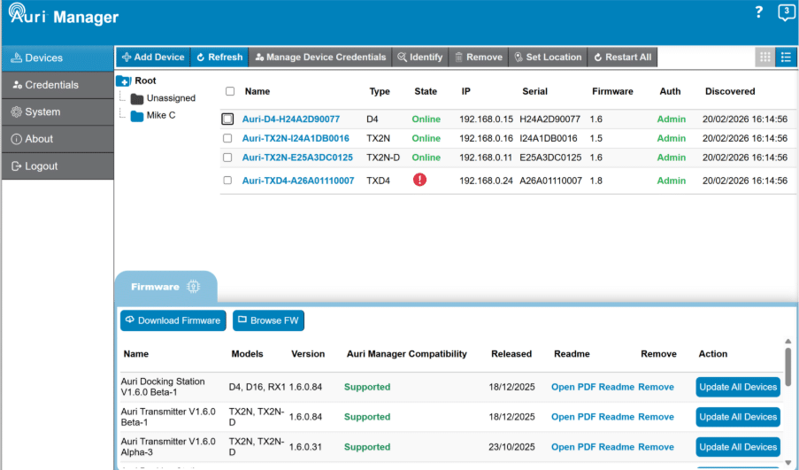
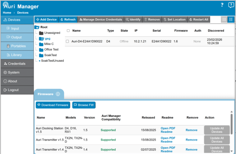
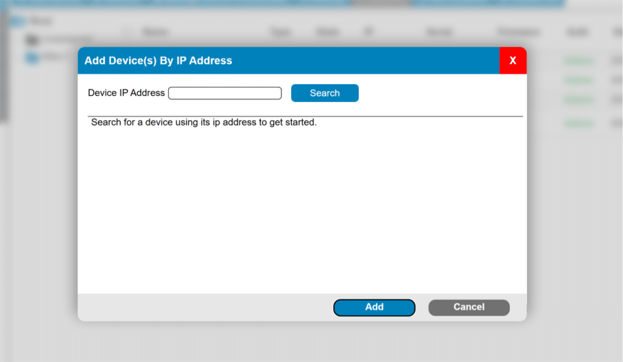
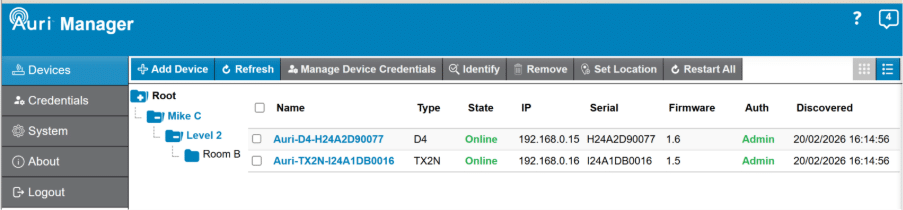



 to open the help text and click anywhere on the page outside the help section or click the help icon again or click the X to reduce this again.